 The present Method Statement was elaborated for the construction of reinforced earth retaining wall and reinforced earth backfills.
Application
This Method Statement does not include the following types/construction sites:
- Retaining walls on accesses to bridges;
- Retaining walls’ top part arrangement (walkway slab);
- Construction of reinforced earth retaining wall and earth backfills at subzero air temperature.
Reinforced Earth Retaining Walls
In order to optimize design solutions and due to land constraints for the designed highway, the Project provides construction of the reinforced earth retaining walls, using synthetic materials.
-
General Provisions.
1.1. This Method Statement regulates work methods and quality monitoring during reinforced earth embankment construction with vertical prefabricated walls.
1.2. This Method Statement provides embankment reinforcing by geo web Fortrac 110/50, 150/50, 200/50 and metal anchors, layer-by-layer backfilling and embankment compaction.
1.3. This Method Statement considers construction of embankment during summertime and at above-zero temperature.
-
Materials required.
Materials, which are required for the construction of the reinforced earth retaining wall, are specified in the working documentation in the table «Specifications on the materials». The list of materials is as follows:
All materials, used for retaining walls and backfills construction must pass the PMT control (including Material Approval Request development).
-
Preparatory works for reinforced earth embankment base and construction of sub base for the retaining wall foundation
3.1. When preparing embankment foundation, its surface shall be first of all cleared of all banked soil and alien things, construction waste, top soil must be removed. Then staking out and fixing the geometry for base and ditch for foundation shall be exercised.
3.2. Then it is necessary to do spot checks of the foundation soil strength by dynamic penetration test to determine softened zones. Dynamic penetration test shall be performed by OAO TsNIIS (Construction Research Institute).
3.3. If any soils with liquidity index ³0,5 or other soils, that fall within “weak soil category” in accordance with point 6.7 SNiP 2.05.02-85 «Highways» are detected, they shall be removed and replaced with medium-grained sand. The removed soil shall be transported to a deposit area. If required, upon the design organization and Client’s approval, the volumes of the removed soil and foundation soil replenishment can be defined based on the results of an investigation, to be carried on by OAO TsNIIS (Construction Research Institute).
3.4. The prepared embankment base course shall be compacted beginning from surface side using sheep foot compactor up to the density ρd = 0,95·ρd max, where ρd max refers to maximum density, reached during standard tests in accordance with GOST 22733-2002.
3.5. After the works’ implementation as per items 3.1. – 3.4., foundation ditch of the retaining wall shall be developed to its design depth. The bottom ditch width shall be at least 2,5 m.
3.6. During ditch development spot soil checks of the ditch bottom shall be exercised in the same manner, as described in items 3.2, 3.3 of the present Method Statement.
3.7. After ditch foundation development and replacement (if necessary) of unusable soil it is necessary to compact the ditch bottom. The density shall make up at least 0,98 ρd max, and in order to reach the desired density along the total layer height, the top layer shall be also compacted by vibro plates.
3.8. 60-cm-high sand layer shall be placed in solid volume on the leveled and compacted ditch bottom along its total width and then be compacted by vibro rollers up to the density of 0,98 ρd max.
3.9. On the prepared and compacted sandy foundation along its total width crushed stone shall be placed, fraction 10-20 mm, height – 0.3 m in solid volume (reserve for the embedding of crushed stone shall make up 0.05 м). The crushed stone layer shall be planned out and compacted using vibro rollers with smooth rolls: first 4 passages along the same trace with out-of-operation vibrator, then 1-2 passages with vibration and 2 passages without vibration.
3.10. The surface of the compacted crushed stone shall be manually leveled up to the design marks of the foundation base and then compacted by 3-4 passages along the same trace by a vibro rollers with smooth roll and powered off vibrator.
3.11. The leveled and compacted crushed stone surface shall be covered along the total ditch width with isolating layer –geo textile material. Geo textile materials shall be sewed to the foundation soil with dowel pins.
3.12. On top of the geo textile the crushed stone under the foundation base shall be covered in overlapping manner with a polymer film in order to prevent penetration of cement paste (mixture) in crushed stone.
3.13. Reinforcing cage and formwork shall be placed on the crushed stone foundation. The monolith reinforced concrete reinforcement slab shall be placed in design locations in concrete by spacers – “cakes”. The expansion joint 40 mm wide shall be set between slabs in increments of 9480 mm, which shall be filled up with the polystyrene foam. After concreting the expansion joint on the polystyrene foam shall be filled up with a sealer.
From the retaining wall face side in slab shall be left reinforcing bars for further installation of monolith reinforced concrete control tooth (fig. 1). Formwork shall be placed with ±5 mm tolerance.
Reinforcement steel as well as concrete shall be approved by the PMT in due order (MAR).

Fig. 1 – Reinforcement bars for control tooth
Main operations under the control during reinforcement works’ implementation, method of control and tolerances are presented in ITP for retaining wall construction.
3.14. Concrete pour shall be done using heavy concrete
Concrete Mx. must correspond to the technical specifications as per GOST 26633-91:B30 F300 W8 according to the design documentation.
It is prohibited to increase a concrete Mx. fluidity by adding of water.
Main operations under the control during reinforcement works’ implementation, method of control and tolerances are presented in ITP for retaining wall construction.
Main operation on concrete quality control, according to STO 36554501-011-2008 are as follows:
Cheque samples of concrete
- test – cube 150x150x150mm must be taken as standard sample.
- samples shall be manufactured and tested in series. Number of samples in a series shall comply with GOST 10180, but at least 4 pc – for strength test in the design life, i.e. 28 days, and at least 2 pc in the intermediate life, i.e. 7 days and in later life.
Sampling and test run
- Concrete mx. samples for cheque samples under the control of concrete strength must be collected according to the requirements of GOST 10181 and TU 5745-227-36554501.
- All samples, designated for various characteristics of concrete must be prepared from one sample of mx. concrete and compacted in equal terms. Deviation of concrete average density of separate series as well as average density of separate samples in each series by the moment of their testing must not exceed 2%.
- Prior to using forms their inner surface must be covered with slim layer of lubricant
- Placing and compacting of concrete mx. must be effected not later than 20 min. after a sample selection.
The samples shall be formed in the following way:
- Forms must be filled with the mx. concrete by layers, not higher than 50 mm. Each layer must be compacted by rodding, using steel rod of Dia 16 mm with oval point. Number of rod pressures shall be estimated on condition that one pressure per 10 cm2 of open surface of the sample. Rodding must be implemented uniformly by helicoidal motion from the edge of the form to the center.
- Form with the placed concrete must be fixed on laboratory vibro plate compactor and must be additionally compacted, using vibration, to the final compaction, characterized by stopping of concrete mx. setting out, smoothing of its surface, upon appearance of slim layer of cement and stopping of bubbling.
- Upon finishing of laying of concrete and concrete mx. compacting in the form the top surface of the sample must be smoothed using trowel or plate.
As soon as the samples are prepared they must be marked. Marking should not damage the sample or impact the results of tests.
Samples curing and storage
- Cheque samples must be fixed directly on the surface of concrete, waterproof coating must be provided.
Forms with samples shall be storage, providing water-heat protection up to the moment of tests.
When the water-heat protection is removed the remaining cheque samples must be striped (free from the forms) and located in the chamber, providing normal conditions for the samples, i.e. temperature of 20 ± 3 Cº and relative air humidity (95±5)%. The samples shall be placed on laying elements so that the distance between the samples as well between the samples and chamber walls be equal at least 5 mm. Area of contact of the sample with the laying elements must be not more than 30% of area of a bearing face of the sample. The samples in the chamber of normal curing must not be watered. It is allowed to keep the samples, covered by wet sand, saw powder and other hygroscopic material.
Testing
- Prior to sample fixing a press bearing plate must be free from concrete particles, remained after the previous tests.
- During compression tests the samples must be positioned as follows: one edge is to be fixed on the bearing plate of the press axially. Marks must be applied on the press plate.
- After fixing of sample on bearing plates of the press (additional steel plates) the top plate must be reconciled with the top bearing plate of the sample so, that their flat area could be fully jointed (one with another). Then loading must be executed.
Load of samples shall be performed continuously with a speed, providing increase of design stress in the sample until it is fully destroyed within the limits of (1,0 ± 0,4) MPa/c.). Meanwhile the load time for a one sample must be at least 30 sec.
- The final force, as a result of testing process, shall be considered as a collapse load and must be recorded in the Test Log.
- Number and location of test areas must be stipulated, keeping in mind:
- control objectives (define class of the concrete, stripping and transfer strength, low strength zone definition etc.); type of constructions; lay-out of steps and a way of concrete pouring; reinforcement of structures.
Herewithб the concrete strength must be monitored at each step of concrete pouring.
3.15. In case the rain threatening arises during concrete pour the protection cover sections must be installed above the place of concrete deposit. At the time of rain the concrete mix. handling and distribution must be stopped.
3.16. Concrete mix. handling and distribution during foundation pour works shall be done by concrete bucket moved with the help of crane.
Upon finishing concrete mix. distribution, process of the concrete mix. compaction shall start using handwork vibrators, equipped with flexible shaft, as well as surface-type vibrator with contemporary correction and redistribution of shaking compression using wood strips according to the designed foundation cross section. At the evidence of initial setting time of the compacted concrete the hand finishing shall begin, using wooden floats and semi-floats.
It is restricted to walk on new concrete.
3.17. When the specific water “shine” disappears on the finished surface, the waterproofing membrane, made of polymer film, must be placed on the concrete surface. Then a layer of non-woven fabric of density about 400 g/m2 shall be arranged. After that one layer of
film must be provided to protect from rain. The cover shall be sand powered to protect it from wind.
3.18. When 75% of the concrete strength (for foundation plates) is achieved it shall be permitted to remove the timbering and start to arrange face walls using wall components CT4-58B with the contemporary reinforcing and filling.
-
Reinforced Earth Retaining Wall Construction
4.1. The works on reinforced earth retaining wall construction shall begin upon 75% of the concrete strength (for foundation plates) is achieved (grade strength compression capacity).
4.2. The remaining surface of the foundation, adjoined with the ground, must be covered with asphalt water-isolation coating mastic.
4.3. The coating waterproof compound shall be arranged in two layers.
Before such works start the isolable surface must be dried, cleaned and refined using compressed air.
4.4. Upon finishing the waterproofing works the first row of wall components CT4-58B of the revetment wall shall be installed.
The first row of components shall be deposited, strictly observing levelness of the upper surface of the wall components.
The wall component CT4-58B is of 580 mm depth, length of face and inner sides is 2380 mm, width is 600 mm. Inside the component there are 4 thru cylinder holes of Ø 426 mm to be filled with crushed aggregate.
The whole length of upper, bottom and edge sides from the side of sloped edge has gutters (R 20) for sticking the joint filler “Abris-S- SH”.
The bottom side of the component has shallow ditches for water flow, drainage on crushed aggregate, and two niches for lifting loops as fixing members. The lifting loops and niches shall be coaxial. The embedded fittings (sleeve pieces) are welded to the block on the construction site.
The inner side of the component shall have two concrete inserts to join the components among themselves and fix metal ties.
Tolerances of geometry of the component and its inserts shall be within the limits of ± 5 mm.
4.5. Prior to the installation the inner face of the component, including the inserts and sleeve pieces, shall be covered by coating waterproof compound. Prior to installation of the first compounds of each row along the vertical side of the component the special joint filler “Abris-S-SH” shall be sticked inside a special gutter for the whole depth of the component (580 mm). After that, the component shall be installed according to the design elevation, pressing it close to the vertical side of the monolithic wall. So, the sticked joint filler finds itself inside the vertical joint between the monolithic wall and the component. Prior to installation of the each nearby component to the end face of the prior component “Abris-S-SH” shall be sticked in a special gutter, which closes the vertical joint between the components. The second component shall be pressed close to the first one, clutching the joint filler between the components.
4.6. Upon installation of the first row components the final sensor monitoring of the correct installation of components shall be implemented: vertical joint sideways the embankment shall be sticked with geo textile, sticked on the waterproof layer.
4.7. Retaining wall “stopping tooth”erection
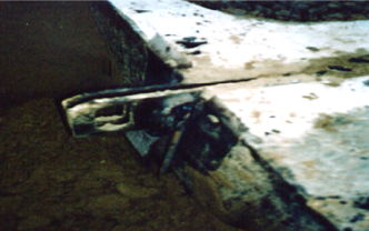
After installation of the first row of components of the revetment wall the base slab of the concrete wall shall get the final skeleton of monolithic reinforced concrete stopping tooth (Drawing 2). Then, timbering of the outer side of the tooth shall be carried out; the stopping tooth shall be embedded in concrete with materials, which meet the requirements of materials for foundation. Before concrete pour the starting bars shall be cleaned from corrosion. Before concrete pour of stopping tooth the base slab surface must be sand-blasted and wetted with water.
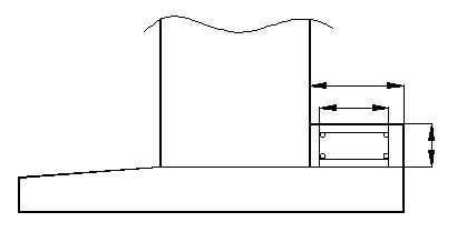
Figure 2 – Stropping Tooth of the Wall
4.8. Before installation of the second row of components CT4-58B and before filling of the first layer of the embankment the cavity pockets of the first row components shall be filled with the crushed aggregate of 10-20 cm fraction up to the half of the component’s depth, using compaction until the setting is stopped, and further on - up to the top. The crushed aggregate compaction shall be implemented by method of vibrating tamper, mass not less than 70 kg, Ø 200-300 mm.
The cavity pockets of the wall components must be filled with the crushed aggregate, in level with the top side of the component. The crushed aggregate surface leveling in the cavity pocket shall be implemented with the help of strips and using flogging-hammer.
4.9. Before installation of second row of the wall components the filling of the first layer of the embankment (sand and crushed prism) shall be implemented at the level of the top side of the components’ first row.
4.10. Crushed prism construction shall be arranged layer-by-layer using three layers each 20 cm, by compacting each layer with vibro platform, mass is not less than 90 kg.
4.11. Prism shoulder shall be covered with Typar SF-32 layer to avoid crushed prism mixing with sand.
4.12. Sand from dumping site to the place of deposit shall be handled by loader, then it shall be leveled by bulldozer and compacted by vibro roller to density not lower than 0,98 pd max. The backfill shall be additionally compacted by vibro plate (90 kg weight) to the width of min. 1,50 m from the inner edge of block. Max. thickness of intermediate layer of sand amounts to 30 cm.
4.13. Shallow ditches for metal ties installation shall be excavated in the crushed stone and in the sand, starting from the components’ joints and at the concrete inserts.
4.14. A screw bolt for concrete inserts of the blocks and anchor should be placed in the middle or in the upper part of sleeve pieces. It is not allowed to place the bolt in the lower part of the sleeve pieces. In such a case it is necessary to make trenches, providing levelling operation and to lay the anchor horizontally. In all circumstances, the running end of the anchor should be higher, than the fixed end.
4.15. It is necessary to cover the anchor with 2 layers of a coating waterproof compound. After its placing, it should be covered by-hand with 5-10 cm sand layer, preventing contact with a geo grid. The surface of sand, being loosened by the vibro roller has to be compacted using vibro platforms.
4.16. Before installation of a second row of the wall components, one should cut a section of the geo grid Fortrac MP (geo-grid nominal size is stipulated for each row in the design documentation) designed length (full width of the embankment, including the wall components width); use the joint filler “Abris C-III”along the horizontal ditch of the first wall components row.
4.17. The geo grid sections are to be spread out, their longitudinal fibres of force, situating perpendicularly to the axis of the road with the excess at least 30 cm only in broadside direction. They are placed on the retaining wall perpendicularly to the fibres, covering the ditch with the joint filler and the apertures of the blocks. After that, they should be fixed with the pegs.
4.18. The second wall components row is to be placed on the geo grid. It is important to monitor and provide the evenness and the horizontality of the first wall components row surface. Blocks’ erection must be implemented under the constant survey control, max. deviation of a wall from the vertical to the backfill side – not more than 5mm/block. Deviation of blocks from the backfill (to the side of a field) is restricted.
The block placing accuracy is± 5 mm.
4.19. The filling up of the second row block cavity is to be made of the crushed stone with the compaction at least at half.
4.20. After the geo grid sections thorough fixing, they are stretched manually one by one and fixed with three pegs at the edge of each section.
4.21. Protective layer of the sand is equals to 0.3 m along the width of the embankment; the inside vertical weld is to be covered by the geo textile Typar SF-32 strings, with the space for the rubble prisms.
4.22. Cavity pockets of the second row of blocks are to be filled and compacted (block holes of the last (top) layer shall be filled with the gravel (in half) to erect monolithic blocks (see item 5). The rubble prisms are to be filled with vibro platforms.
4.23. Typar SF – 32cloth is to cover the prism shoulder.
4.24. The layer of sand is to be filled and planned according to the reference mark of the next wall components row. It is compacted with the tamper (at least 0.98rd max). *The top (per height) layer of the backfill shall be additionally compacted using surface smoothing roller.
4.25. The techniques of the reinforced embankment layer construction are similar to that of the second layer.
4.26. In order to ensure the water drainage from behind the wall (level of blocks’ row is given in the Design Documentation), the geomembrane layer is to be laid along the wall at the level of the third wall blocks raw. The perforated polymeric pipe is to be placed on the layer with the asbestos-cement outlets on the other side of the wall. The increment for the outlets is 9480 mm.
4.27. Three last rows of the wall components are to be fastened together by welding of the armature of AIII type (Æ20 mm to the sleeve pieces of each wall component underlying row; the geo grid is to be protected by a sand layer, when implementing the welding works (Picture №3,Picture №4). The necessity to join the last three wall blocks rows directly depends on the wall height (if the height is less than 2 meters, that won't be necessary; if it is more than 2 meters - it is necessary).
4.28. Options for the retaining wall top structure will be inserted into this Method Statement, to be submitted later on.

Picture 3 –Geo grid is covered with the sand.
Picture 4 – Welding of the last three top rows of RW blocks.
-
Monolithic Smoothing Bar
5.1. Prior to starting of works on monolithic smoothing bar arrangement the subsequent operation must be implemented – p.4.8 - 4.23 for construction of the last (top) block of the earth reinforced retaining wall (filling the block holes with the gravel with compaction by half).
5.2. A reinforcing cage and casing must be arranged on the gravel base. The design location of a monolithic reinforced concrete slab in the concrete shall be provided by erecting spacer – “crackers”.
The expansion joint 20 mm wide shall be set between slabs in increments of 9480 mm, which shall be filled up with the polystyrene foam. After concreting the expansion joint on the polystyrene foam shall be filled up with a sealer.
Reinforcement steel as well as concrete shall be approved by the PMT in due order (MAR).
The main operations controlled during production reinforcement and concrete works of are described in the ITP on the construction of reinforced walls.
For the main operations on concrete quality control see the paragraph of the present plan about the construction of reinforced-concrete monolithic foundation.
5.3. After construction of monolithic smoothing bar the last layer of reinforced earth embankment is filled up and smoother roller is used for the surface leveling (paragraph 4.24. of the present plan).
-
Safety arrangements.
6.1. When performing the works the requirements of the Branch Construction Norms 8-89 are to be followed («Instruction on Environmental Protection during the Construction, Repair and Operation of Roads»). Engineering workers, operators of the construction equipment, dumpers drivers and road workers should pay special attention to the following points:
It is impossible to apply the materials for the sub grade construction which affect the environment , earthworks and soil storage outside the permanent or temporary land allocations are prohibited;
One should prevent ground, water and atmosphere pollution (dust, toxic gas from engines, solid discharge, volatile products after evaporation, noise, vibration etc.).
6.2. Heads of organizations are to provide the employees with overall, safety shoes and other personal protective equipment in accordance with the standard norms of the branch.
6.3. At the construction site it is prohibited to be without protective helmets in accordance with GOST 12.4.087-80.
6.4. When carrying out the assembling works unauthorized persons must not be admitted to a site as well as other works cannot be performed.
6.5. Materials, structures and equipment must be stored in accordance with the standards requirements for materials, structures and equipment.
6.6. When constructing the embankment one should meet the H&S requirements stated in item 1.4.
6.7. Operation and maintenance of the construction vehicles must be done in according with GOST 12.3.033-84 and the manuals of manufacturing plants.
6.8. Road construction vehicles can work in the area of power transmission lines and underground utilities only if an operator has a permit for the works performance.
Before the works start signs pointing out the location of underground facilities must be arranged.
6.9. Before the embankment works start the approaches must be provided to make it possible for the vehicles to reach the construction site.
6.10. When positioning and moving the construction vehicles and machinery one should take proper measures to prevent it from random movement and turnover under action of gravity and external forces.
6.11. A dumper may drive no more than 50 m in reverse to reach the place of shipping and unloading moreover there must be horns beeping. Vehicles may drive in reverse in the area of work performance only under command of involved persons.
6.12. Soil compaction by vibro rollers should be done not closer than 1,5 m from the retaining walls to prevent a vehicle from slipping down.
6.13. One should observe the following rules:
geo textile and geo grid rolling-off as well as applying of geo syntheticс materials must be done by a team of two or more workers;
geo synthetic material should be backfilled in the section not closer than 20 m from a place of rolling-off or a place of sub grade junction;
cutting of geo textile materials should be done from the worker’s body away, a cutting tool should be kept in a case.
-
Environmental Protection
Retaining wall works shall be performed in the area of especially protected natural value. Special nature protection measures must be taken, described in the GC’s Environmental Plan MOST EVS 000000 0001 and in the Especially Protected Natural Areas Management Plan PLA MOST EMS 000000 0004.
Prior to the works start the environment briefing must be conducted with all the employees, involved in the works.
Road building machinery and equipment must stay located on the site only during the period of appropriate works implementation. Storage of not-in-use, write-off machines or machines (or their parts and aggregates), liable to be repaired in stationary conditions, is not allowed within the on-site areas of temporary allocated sites.
The operating road machines impact the environment in the part of air pollution with flue gas, dust and vehicle emissions, also the road machines are like noise and vibration source for the surrounding areas.
Level of pollution from the road machines, mechanisms and vehicles must not be higher than maximum allowable concentration of hazardous substances for air, water, as well as maximum allowable level of noise impact for buildings and territories of different economic kinds. All the above listed must comply with sanitary norms and meet the safety requirements during the works implementation.
Parameters of machines, equipment, vehicle in use during construction period and in the part of flue gas, vibration and other environment impact must correspond to the standards and technical conditions in force in the enterprises-manufacturers, and approved by sanitary authorities.
Cleaning and washing of carriage bodies of dump truck and concrete lorry must be exercised only in the places, specially provided for such purposes. After-washing water must be delivered to special sedimentary basins for its second utilization, water discharge to the water bodies is prohibited.


